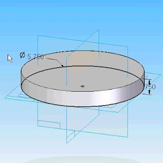
Overview: Protrusions are features that add material to a solid. In the previous topics, we discussed the feature creation process. Now let's look at some of the options for protrusions.
Protrusion as a Base Feature.
When you are creating the base feature in the part with a protrusion, there are two extent options available. The default option is called Finite Extent. This option defines the extrusion with a distance value from the profile. To define the distance, you have three options.Option 1 is to drag the cursor to the approximate location and pick the location in the graphics window.
Option 2 is to type in a value in the Distance text box and press ENTER on the keyboard. After the distance is entered, pick the location to determine the direction of the protrusion.
Option 3 is to pick a key point. The key point option can be end point, mid-point, arc center, or tangent point on the solid. The protrusion is then linked to that key point, and is modified when the key point moves.
The second extent option available is called From/To Extent. This option defines the length of the protrusion as the distance between the 'From' surface or plane, and the 'To' surface or plane. When creating the base feature, you will typically use the Finite Extent option
Tomorrow we will see Additional Protrusions ,Symmetrical/Non-Symmetrical & Treatment Features the continuation of this topic.
The video for overview of Protrusions will be posted on tomorrow.
Please Give comments.

No comments:
Post a Comment
Please comment this post to improve this blog