Completion Time: 45 Minutes
Objective: Apply the techniques you learned in this chapter. During this project, you are going to create two sketch profiles. You will practice using drawing tools like lines, arcs, ellipses, and trimming. In addition, you will apply the required geometric constraints to hold the profiles to the desired shape. You will then create the necessary dimensions to create a fully constrained profile.
Instructions
1: Create a new metric part. Save the part and name it advanced_profiles.par. Place the file in a location where you have permission to save parts.
Step 1 - Details
1.1 Click File | New.
1.2 Select the More tab on the New dialog.
1.3 Pick Normet.par from the Templates list.
1.4 Click File | Save.
1.5 Click OK on the File Properties dialog.
1.6 Use the Look In option to navigate to a folder for where to save the part.
1.7 Enter advanced_profiles in the File name box.
1.8 Click OK to save the part.
2: Create the first sketch. Place the sketch coincident with the Top plane.
Step 2 - Details
2.1  Click Sketch.
2.2 Click Coincident Plane from the Plane pull-down on the ribbon bar.
2.3 In the Graphics window, pick the Top plane.
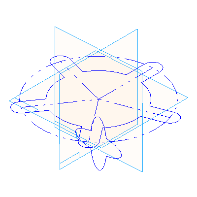
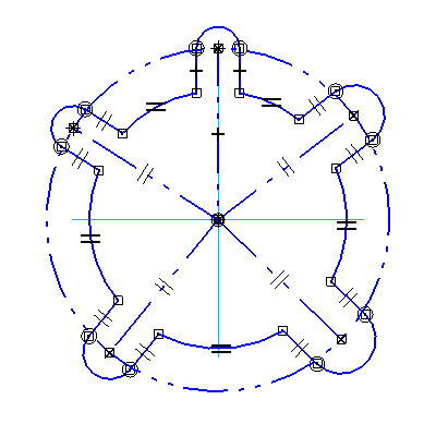
3: Create the geometry for the profile. Start by drawing a circle with the center attached to the mid point of the reference plane. Next create five tabs as depicted in the graphic. 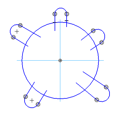
Trim the profile to complete the main portion of the geometry
Step 3 - Details
3.1  Click Circle by Center from the Circle fly-out on the Draw toolbar.
3.2 Move the cursor over the intersection of the two reference planes. Pick the midpoint of either reference plane.
3.3 Move the cursor to create the circle. Pick the location to create the circle so it is just inside the reference planes.
3.4  Click Line on the Line fly-out on the Draw toolbar.
3.5 Start at the top of the circle and create a vertical line, an arc, and another vertical line. The profile should look similar to the following graphic. 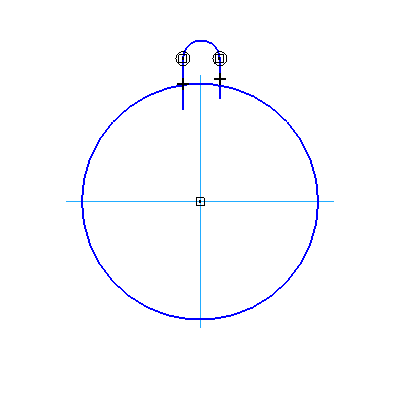
Right-click after the profile is drawn.
3.6 Create four additional tabs just like the last one you just created. The profile should look similar to the following graphic.
![clip_image009[1]](http://lh3.google.com/udhaya1413/R9jtBQ2F0nI/AAAAAAAAB8k/G05b70MNxdI/clip_image009%5B1%5D_thumb%5B2%5D)
3.7  Click Trim on the Draw toolbar. Hold the left mouse button down and drag the cursor across the curves in the graphic.
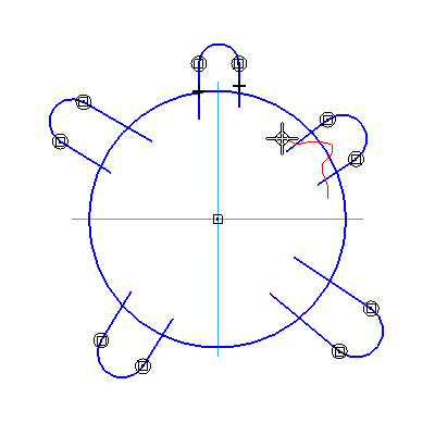
Release the left mouse button to complete the trim.
3.8 Repeat the process for the four remaining tabs. The profile should look similar to the following graphic.
![clip_image010[1]](http://lh5.google.com/udhaya1413/R9jtKw2F0tI/AAAAAAAAB9U/SUtXfs8VbO4/clip_image010%5B1%5D_thumb%5B2%5D)
4: Create the construction geometry for the first profile. Start by creating a circle that is larger that the first circle drawn in the previous step. Then create a series of lines. Each line is to start at the center of the profile and terminate at the arc center of each tab. There should be five lines total.
After the curves are created, convert them to reference geometry.
Step 4 - Details
4.1 ![clip_image011[1]](http://lh6.google.com/udhaya1413/R9jtSA2F0zI/AAAAAAAAB-E/tIaZFTBE0UI/clip_image011%5B1%5D_thumb) Click Circle by Center from the Circle Fly-out on the Draw toolbar.
Click Circle by Center from the Circle Fly-out on the Draw toolbar.
4.2 Pick the location for the center of the circle near the center of the profile.
4.3 Pick the location of the diameter just inside the tabs, but outside the circle.
4.4 ![clip_image012[1]](http://lh4.google.com/udhaya1413/R9jtUg2F01I/AAAAAAAAB-U/kXW3a6oQgDE/clip_image012%5B1%5D_thumb) Click Line on the Line Fly-out on the Draw toolbar.
Click Line on the Line Fly-out on the Draw toolbar.
4.5 Pick the mid point of the reference plane for the start of the line and pick the arc center of one of the tabs.
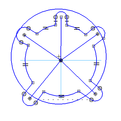
4.6 Create a line for all five tabs. The profile should look similar to the following graphic.
4.7 Click Construction on the Draw toolbar.
4.8 Pick the circle. Notice the font changes to phantom.
4.9 Pick the five lines. The profile should look similar to the following graphic.
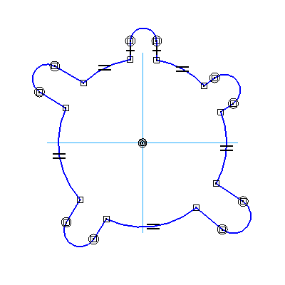
5: Apply Geometric Constraints for the first profile. There are several constraints to apply, here is the basic rundown:
Make all lines for the tab tangent to the arc on the tab.
Make the short lines on the tab parallel to each other,
Make the centerline for each tab parallel to one of the lines on the tab.
The arcs on the top of each tab are of equal length.
Make the construction circle concentric to center of the profile.
Connect the arc center of each tab to the construction circle.
Make sure the lines for to the tab at the top of the profile are vertical.
The profile should look similar to the graphic.
Step 5 - Details
5.1  Click Tangent on the Features and Relationships toolbar. Pick a short line on the tab and select the small arc. Repeat the process for all tabs that do not have a tangent constraint applied.
5.2  Click Parallel on the Features and Relationships toolbar. Pick the short line on one side of any angled tab and then pick the other short line. Repeat the process for all angled tabs.
5.3 ![clip_image021[1]](http://lh3.google.com/udhaya1413/R9jtfQ2F09I/AAAAAAAAB_U/JNkjujCchvQ/clip_image021%5B1%5D_thumb) Click Parallel on the Features and Relationships toolbar. Pick the short line on one side of any angled tab and then pick the long line that runs to the center of the profile. Repeat the process for all angled tabs.
Click Parallel on the Features and Relationships toolbar. Pick the short line on one side of any angled tab and then pick the long line that runs to the center of the profile. Repeat the process for all angled tabs.
5.4  Click Equal on the Features and Relationships toolbar. Pick the arc on the top tab and pick the arc on the next tab. Repeat the step until all arcs are equal to each other.
5.5  Click Concentric on the Features and Relationships toolbar. Pick the construction circle and pick the arc that is connected to the center of the reference planes.
5.6  Click Connect on the Features and Relationships toolbar. Pick the arc center of a tab and pick the construction circle. The cursor should indicate that you are selecting a Point on Curve when you pick the construction circle. Repeat the process for all five tabs.
5.7 Inspect the three vertical lines at the top tab. Make sure each of them have a plus (+) sign at the mid point of each line. If they do not, click Horizontal – Vertical Relationship on the Features and Relationships toolbar. Pick each line that requires the constraint.
5.8 The profile should look similar to the graphic.
![clip_image019[1]](http://lh5.google.com/udhaya1413/R9jtpw2F1FI/AAAAAAAACAU/UXkKUjCKF7c/clip_image019%5B1%5D_thumb%5B2%5D)
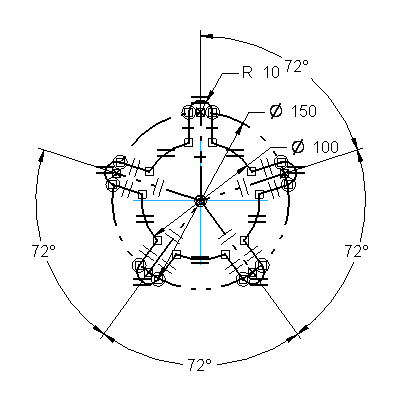
6: Apply dimensions to the first profile. Use the graphic as a reference for the size of the profile.
Step 6 - Details
6.1  Click Smart Dimension on the Draw toolbar. Pick the arc on any of the tabs. Move the cursor to display the dimension. Pick the location for the dimension. Enter 10 for the size of the radius and press ENTER.
6.2 Pick the construction circle. Move the cursor to display the dimension. Pick the location for the dimension. Enter 150 for the size of the diameter and press ENTER.
6.3 Pick an arc that is segmented by a tab.  Activate Diameter on the ribbon bar. Move the cursor to display the dimension. Pick the location for the dimension. Enter 100 for the size of the diameter and press ENTER.
6.4  Click Angle Between from the Dimension Between Fly-out on the Draw toolbar. Pick the vertical construction line. Pick the construction line for the tab in the upper-right side of the profile. Move the cursor to display the dimension. Pick the location for the dimension. Enter 360/5 for the size of the angle and press ENTER.
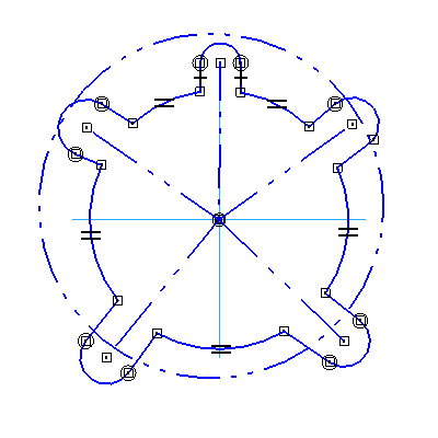
6.5 Select the construction for the next tab that is in a clockwise direction. Move the cursor so the dimension is chained from the last dimension. Pick the location for the dimension. Enter 360/5 for the size of the angle and press ENTER. Continue picking construction lines and entering the value until the profile is complete. Once complete, the profile should be completely black. The completed profile should look similar to the following graphic.
![clip_image025[1]](http://lh4.google.com/udhaya1413/R9juEg2F1PI/AAAAAAAACBk/IY-VfOZHwe8/clip_image025%5B1%5D_thumb%5B2%5D)
7: Finish the first sketch and save the part.
Step 7 - Details
7.1  Click Return on the ribbon bar.
7.2  Click Finish on the ribbon bar.
7.3 Click File | Save.
8: Create the second sketch. Place the sketch coincident with the Front plane.
Step 8 - Details
8.1 ![clip_image008[1]](http://lh3.google.com/udhaya1413/R9juLQ2F1VI/AAAAAAAACCU/fJF-gXqwcS8/clip_image008%5B1%5D_thumb) Click Sketch.
Click Sketch.
8.2 Click Coincident Plane from the Plane pull-down on the ribbon bar.
8.3 In the Graphics window, pick the Front plane.
9: Create the curves for the second profile. The second profile consists of two ellipses, one at 0 degrees and one at 90 degrees. The two ellipses share the same center point. 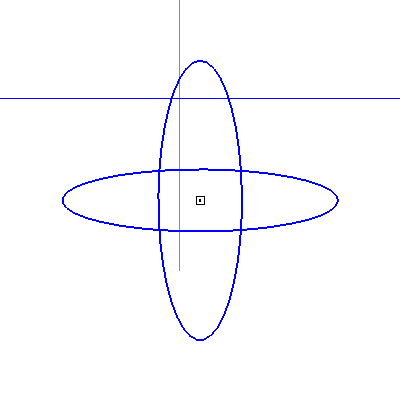
Trim the center portions of the profile away so you are left with four partial ellipses. The completed profile should look similar to the following graphic. 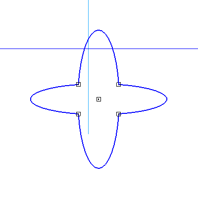
Step 9 - Details
9.1  Click Ellipse by Center from the Circle fly-out on the Draw toolbar.
9.2 Pick the location for the center of the ellipse somewhere below the horizontal reference plane. Enter 0 in the Angle text box and press ENTER. Drag the cursor to the left of the origin. Pick the location of the primary axis. Move the cursor up and pick the location of the secondary axis.
9.3 Create a second ellipse at the arc center of the first ellipse. Enter 90 in the Angle text box and press ENTER. Pick the location of the primary axis, then the secondary axis.
9.4 ![clip_image015[1]](http://lh6.google.com/udhaya1413/R9juSA2F1dI/AAAAAAAACDU/vQIuRhb3DhU/clip_image015%5B1%5D_thumb) Click Trim on the Draw toolbar. Hold the left mouse button down and drag the cursor across the curves in the graphic. Release the left mouse button to complete the trim.
Click Trim on the Draw toolbar. Hold the left mouse button down and drag the cursor across the curves in the graphic. Release the left mouse button to complete the trim. 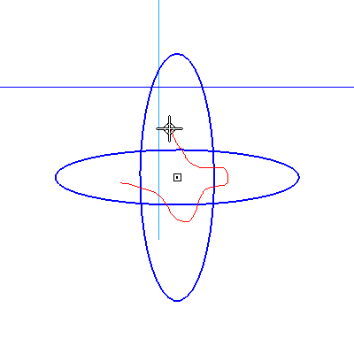
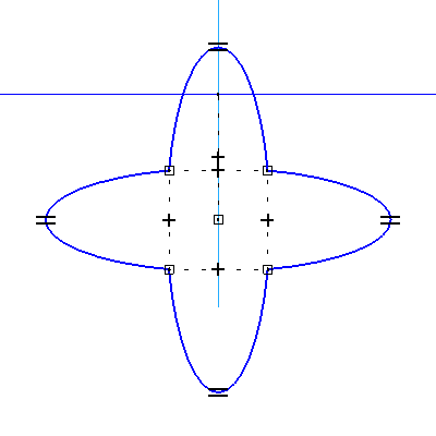
10: Create the geometric constraints for the second profile. There are several constraints to apply, here is the basic rundown:
Connect the centers of all four ellipses.
Make all four ellipses equal to each other.
Align the four corners of each ellipse both horizontally and vertically.
Make the center of the ellipses align vertically with the mod point of the reference plane.
The profile should look similar to the graphic.
Step 10 - Details
10.1 ![clip_image024[1]](http://lh5.google.com/udhaya1413/R9juZw2F1jI/AAAAAAAACEE/bpjcugb6OLw/clip_image024%5B1%5D_thumb) Click Connect on the Features and Relationships toolbar. Pick the arc center of an ellipse and pick the arc center of a second ellipse. Repeat the process for all four ellipses
Click Connect on the Features and Relationships toolbar. Pick the arc center of an ellipse and pick the arc center of a second ellipse. Repeat the process for all four ellipses
10.2 ![clip_image022[1]](http://lh6.google.com/udhaya1413/R9jucA2F1lI/AAAAAAAACEU/FxlqtkH3Pj0/clip_image022%5B1%5D_thumb) Click Equal on the Features and Relationships toolbar. Pick the ellipse on the top and pick the ellipse on the right. Repeat the step until all ellipses are equal to each other.
Click Equal on the Features and Relationships toolbar. Pick the ellipse on the top and pick the ellipse on the right. Repeat the step until all ellipses are equal to each other.
10.3  Click Horizontal – Vertical Relationship on the Features and Relationships toolbar. Pick the end point of an ellipse and pick a second end point of a second ellipse. The two points should align horizontally or vertically. Repeat the process for all four corners. You should see a dashed box connected to all four corners of the profile. Each leg of the box should have a plus (+) sign in the middle of it.
10.4 ![clip_image036[1]](http://lh5.google.com/udhaya1413/R9juhw2F1pI/AAAAAAAACE0/ahtZruBBrHc/clip_image036%5B1%5D_thumb) Click Horizontal – Vertical Relationship on the Features and Relationships toolbar. Pick the arc center of an ellipse and pick the mid point of the reference plane. The two points should align vertically. The profile should look similar to the following graphic.
Click Horizontal – Vertical Relationship on the Features and Relationships toolbar. Pick the arc center of an ellipse and pick the mid point of the reference plane. The two points should align vertically. The profile should look similar to the following graphic.
![clip_image035[1]](http://lh4.google.com/udhaya1413/R9jukg2F1rI/AAAAAAAACFE/ORqreE-3g3w/clip_image035%5B1%5D_thumb%5B2%5D)
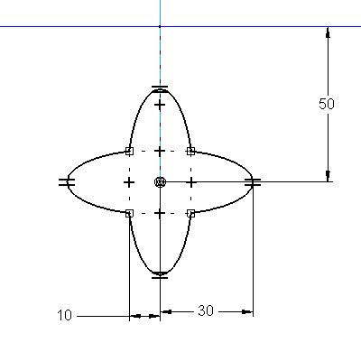
11: Create the dimensions for the second profile. Use the graphic as a reference for the size of the profile.
Step 11 - Details
11.1 ![clip_image026[1]](http://lh5.google.com/udhaya1413/R9juqw2F1vI/AAAAAAAACFk/2N2GSyVs4H8/clip_image026%5B1%5D_thumb) Click Smart Dimension on the Draw toolbar. Pick the horizontal reference plane and pick the arc center of any ellipse. Move the cursor to display a vertical dimension. Pick the location for the dimension. Enter 50 for the size of the dimension and press ENTER.
Click Smart Dimension on the Draw toolbar. Pick the horizontal reference plane and pick the arc center of any ellipse. Move the cursor to display a vertical dimension. Pick the location for the dimension. Enter 50 for the size of the dimension and press ENTER.
11.2 Pick the lower end point of the ellipse on the left and pick the arc center of any ellipse. Move the cursor to display a horizontal dimension. Pick the location for the dimension. Enter 10 for the size of the dimension and press ENTER.
11.3  Activate Select Tangency on the ribbon bar. Pick the tangency of the right ellipse and pick the arc center of any ellipse. Move the cursor to display a horizontal dimension. Pick the location for the dimension. Enter 30 for the size of the radius and press ENTER.
12: Finish the second sketch and save the part.
Step 12 - Details
12.1 ![clip_image029[1]](http://lh3.google.com/udhaya1413/R9juvQ2F1zI/AAAAAAAACGE/OmWlGZuiz0A/clip_image029%5B1%5D_thumb) Click Return on the ribbon bar.
Click Return on the ribbon bar.
12.2 ![clip_image030[1]](http://lh3.google.com/udhaya1413/R9juxQ2F11I/AAAAAAAACGU/GLXytjuRebw/clip_image030%5B1%5D_thumb) Click Finish on the ribbon bar.
Click Finish on the ribbon bar.
12.3 Select File | Save.
Review: You should have more confidence in working with profiles after completing this project. Working with ellipses in a profile can be frustrating, but with a little patience, you can get the results you are looking for. Remember to always try and create a fully constrained sketch and be sure to capture your design intent.

 Axis of Revolution