Monday, April 28, 2008

Filleting Profiles - SolidEdge

Filleting Profiles

clip_image002

clip_image004

Use this to ...

  • Round corners in a profile.
  • Play the video to learn how to create two fillets using two different methods. Do not adjust your volume; there is no sound associated with this video.

Key Points

  • Creates a tangent arc between two curves in profile.
  • Use this option as a last resort. Use a round feature on the model afterwards.

Prerequisites

  • Solid Edge must be in the profile mode. Profile is automatically activated when creating a sketch feature or creating a profile for a feature.

Process: Dynamically Creating a Fillet on a Profile

1. clip_image004[1] Click Fillet from the Fillet fly-out on the Draw toolbar.

clip_image011

2. clip_image012 If necessary, click No Trim on the ribbon bar.

3. In the Graphics window, pick the first curve to highlight it.

4. Pick the second curve to highlight it and display the fillet.

5. Move the cursor to the desired location.

6. Pick to create the fillet.

Process: Creating a Fillet on a Profile by Dragging

1. clip_image004[2] Click Fillet from the Fillet fly-out on the Draw toolbar. clip_image011[1]

2. In the Graphics Window, hold left mouse button close to one of the curves to fillet.

3. Drag the cursor across the two curves.

4. Release left mouse button to create the fillet.

Tips

  • It is strongly encouraged to apply fillets as round features in the model. This practice gives you more flexibility for editing, deleting, or redefining the fillet.
  • Dragging across the two lines you want to modify also places a fillet. This modifies the lines to the cursor's approximate intersect position; however, this is very inaccurate.
  • The two curves being modified don't have to connect to perform this operation. The Fillet operation connects the two curves to the fillet.

Friday, April 25, 2008

Sketch Tools- SolidEdge

Ellipse

An ellipse creates a circle that is shortened on one axis. They can be handy in a profile, but can also be a little tricky to constrain. There are two methods for creating an ellipse, By Center and By Three Points. Either method uses the same technique for creating them. When you create an ellipse, you pick the first location of the ellipse, pick the location of the primary axis, then pick the location of the secondary axis.

clip_image003

Trimming

It is sometimes required to trim curves that overlap or need extending. The Trim functions on the Draw toolbar provide the capability of trimming curves. The command trims back the portions of curves that are selected. This can be done by picking curves individually or by dragging the cursor across the curves to remove. The trim options also apply geometric constraints to the trimmed curves. Using the trim options can be very useful when importing profiles from other CAD packages, such as AutoCAD.

clip_image004

clip_image005

Construction Curves

There are times when you need to create curves in a profile that are helpers in constraining a profile. These curves are called construction curves. To create a construction curve, simply create the required curve or curves as regular geometry. After the geometry is created, you convert the geometry using Construction. This option converts regular curves to construction curves. After the curves are converted, they display in a phantom line font. Construction can also convert a construction curve back into a regular curve.

clip_image006

Tuesday, April 22, 2008

Profile Basic - SolidEdge

Profile Basic - SolidEdge

clip_image002


In this unit ...

  • The advanced profile creation unit exposes you to more complex curves and constraints. This unit provides you with different techniques for quickly creating curves, constraints, and dimensions. In addition, you will learn additional tips for modifying a profile. Play the video for an overview of what will be covered in this unit. This is a sound video, so please adjust your volume accordingly.
  • This unit: - Introduces you to more profile terminology and settings. - Shows you how to create the additional curves. - Demonstrates how to apply more constraints on a profile. - Shows how to rapidly dimension a profile. - Demonstrates how to modify a profile.

Prerequisites

  • Basic Profiles knowledge

Completion Time: 2 hours

Advanced Profiles Overview

clip_image007

Overview: There are several curve types available when creating a profile. The Advanced Profile Creation unit exposes you to most commonly used curve types. In the next few topics, you will be shown how to use these curve commands. Play the video to see an overview of the advanced tools available when creating a profile. This is a sound video, so please adjust your volume accordingly.

Rectangle

Located on the Draw toolbar, Rectangle creates a series of 4 lines. There are two different methods for creating a rectangle. The fastest method is by dragging the cursor across the graphics window. A rectangle is created between two locations of the drag. The second method uses three points. The first point is the base point, the second point defines the length of the rectangle, and the third point defines the height of the rectangle. This is useful for creating rectangles at an angular orientation.

clip_image010

Monday, April 21, 2008

Project: Basic Profile Creation Project - SolidEdge

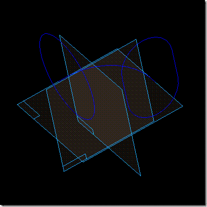
Project: Basic Profile Creation Project
clip_image002

Completion Time: 30 Minutes

Objective: Complete the three sketches to re-enforce the topics described in this unit.


Instructions

1: Create a new metric part in a location where you can save parts. Save the part and name it flanged_elbow.

Step 1 - Details

1.1 Click File | New.

1.2 Select the More tab and select Normet.par from the list.

1.3 Click OK on the New dialog.

1.4 Click File | Save.

1.5 Click OK on the Properties dialog.

1.6 Use the Look In option to navigate to the folder where the part is top be saved.

1.7 Type in flanged_elbow in the file name text box.

1.8 Click OK on the Save As dialog.

2: Create the first sketch Top plane. The profile consists of an arc with two small lines on each side. The arc center is constrained to the mid point of one of the reference planes and the ends of the arc are connected to the corresponding reference plane. The two short lines are both 10mm long. Complete this profile to the shape and size of the following picture. clip_image008
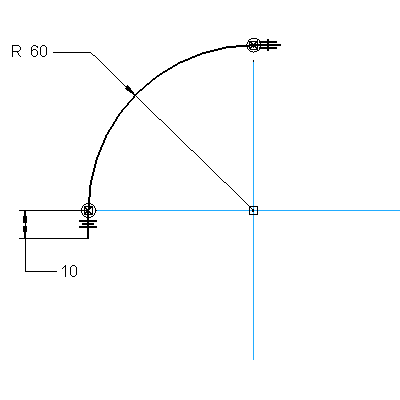
Step 2 - Details

2.1 clip_image009 Click Sketch from the Features toolbar.

2.2 Pick the Top plane in the graphics window.

2.3 clip_image010 Click Line on the Draw toolbar.

2.4 Draw the following curves. clip_image012
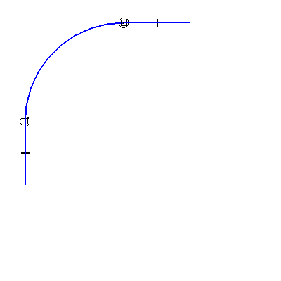
2.5 clip_image013 Click Tangent. Apply tangency between all lines and arcs that do not have it.

2.6 clip_image014 Click Connect. Pick the arc center and the mid point of the reference plane. Pick the endpoint of the lower portion of the arc and select the horizontal reference plane. Pick the endpoint of the upper portion of the arc and select the vertical reference plane.

2.7 clip_image015 Click Equal. Pick the two small lines.

2.8 clip_image016 Click Smart Dimension. Pick the arc and dimension it to a value of 60mm. Pick one of the lines and dimension it to a value of 10mm.

2.9 Click Return on the ribbon bar.

2.10 Click Finish on the ribbon bar.

3: Create the second sketch on the Front plane. The profile consists of a circle. The circle is connected to the end point of one of the short lines in the first sketch. Complete this profile to the shape and size of the following picture. clip_image017
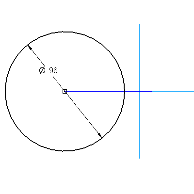
Step 3 - Details

3.1 clip_image009[1] Click Sketch from the Features toolbar.

3.2 Pick the Front plane in the graphics window.

3.3 clip_image010[1] Click Circle by Center from the Circle Fly-out on the Draw toolbar.

3.4 Draw the following circle. clip_image018
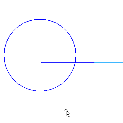
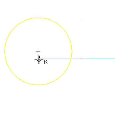
3.5 clip_image014[1] Click Connect. Pick the circle center and the end point of the short line from the first sketch. The cursor should look like this when you select the end of the curve. clip_image019
3.6 clip_image016[1] Click Smart Dimension. Pick the circle and dimension it to a value of 96mm.

3.7 Click Return on the ribbon bar.

3.8 Click Finish on the ribbon bar.

clip_image006[4]

4: Create the third sketch on the Right plane. The profile consists of two lines and two arcs in the shape of an oval. The arc centers are aligned vertically with the end point of one of the short lines in the first sketch. The mid points of the lines are aligned horizontally with the mid point of the Top plane. Complete this profile to the shape and size of the following picture. clip_image020
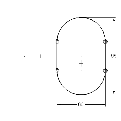
Step 4 - Details

4.1 clip_image009[2] Click Sketch from the Features toolbar.

4.2 Pick the Right plane in the graphics window.

4.3 clip_image010[2] Click Line on the Draw toolbar.

4.4 Draw the following curves. clip_image021
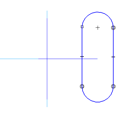
4.5 clip_image013[1] Click Tangent. Apply tangency between all lines and arcs that do not have it.

4.6 clip_image022 Click Horizontal – Vertical. Pick the arc center the top arc and pick the end point of the short line in the first sketch. Pick the mid point of the left vertical line and pick the mid point of the reference plane.

4.7 clip_image016[2] Click Smart Dimension. clip_image023 Activate Tangent Display in the ribbon bar. Pick the top arc and the bottom arc and dimension it to a value of 96mm. Pick the left vertical line and the right vertical like and dimension it to 60mm.

4.8 Click Return on the ribbon bar.

4.9 Click Finish on the ribbon bar.

5: When you have completed the sketches, save the part. Remember the location of this part for future use.

Step 5 - Details

Click File | Save.


Challenge Task: To ensure the second and third profiles are connected to the first profile, edit a dimension in the first profile. Modify the radius dimension to a value of 120mm. Look to see if the second and third profiles move with the change. If not, revisit the profiles and set the connection to the first profile.


Review: In this project, we positioned the second and third profiles relative to the first profile. If the first profile is modified, the location of the other two will automatically update. This is an effective method for capturing Design Intent.

Saturday, April 19, 2008

Editing Dimensions - SolidEdge

Editing Dimensions

clip_image002

clip_image004

Use this to ...

  • Modify the values of the dimensional constraint that controls the size of your model.
  • Move the origin of a dimension.
  • Add appended text or tolerance information.
  • Play the video to see how to edit existing dimensions by changing the values and adding appended text. Do not adjust your volume; there is no sound associated with this video.

Prerequisites

  • Solid Edge must be in the Profile mode. The Profile mode is automatically activated when creating a sketch feature or creating a profile for a feature.

Process: Changing Feature Dimensions

1. clip_image004[1] Click Select Tool on the Draw toolbar.

2. Pick the dimension to edit in the Graphics window. The edit dimension ribbon bar displays.

3. In the Dimension Value box, enter avalue and press ENTER.

4. If required, set the dimension type or inspection options from the ribbon bar.

5. If required, set the appended text options for the dimension.

6. Continue selecting dimensions until all desired dimensions are changed.

Process: Moving Dimensions in the Profile

1. clip_image004[2] Click Select Tool on the Draw toolbar.

2. Pick the dimension to edit in the Graphics window. The edit dimension ribbon bar displays.

3. Click and hold over the dimension line of the selected dimension.

4. Move the dimension to the desired location. Release to place the dimension.

5. Continue to select dimensions and place them at the desired locations.

Tips

  • It's usually easier to pick the feature to edit from the Edgebar rather than the Graphics window.

Wednesday, April 16, 2008

Distance Between - SolidEdge

Distance Between

clip_image002

clip_image004

Use this to ...

  • Dimension between elements in a profile showing the linear distance between the selections.
  • Create stacked dimensions quickly.
  • Play the video for a demonstration of how to create a stacked set of dimensions, all from a single origin. Do not adjust your volume; there is no sound associated with this video.

Key Points

  • This option is great for placing a series of dimensions quickly.

Prerequisites

  • Solid Edge must be in the Profile mode. The Profile mode is automatically activated when creating a sketch feature or creating a profile for a feature.

Process: Creating Dimensions Between Curves

1. clip_image004[1] Click Distance Between on the Distance Between fly-out on the Draw toolbar. clip_image001[1]clip_image010

2. If necessary, select the appropriate option from the Orientation list on the ribbon bar.

3. Pick the first curve in the Graphics window. This is the base location of the dimension set.

4. Pick the second curve in the Graphics window. The dimension outline displays.

5. Pick the location of the first dimension in the Graphics window.

6. If desired, pick a third curve in the Graphics window. The dimension outline displays.

7. Pick the location for the second dimension. Solid Edge creates stacked dimensions depending on the cursor position in the Graphics window.

8. Continue picking elements and placing the dimensions in the Graphics window. The dimensions continue the placement style.

9. Right-click in the Graphics window to finish or select a new base location.

Tips

  • If you are having difficulty trying to place a dimension tangent to a circle or arc, try picking just to either side of where you had been picking on the circle or arc (pick off the axis).

Monday, April 14, 2008

Smart Dimension - SolidEdge

Smart Dimension


clip_image002


clip_image004


Use this to ...

  • Create a dimension on a selected profile curve.
  • Create a dimension between selected profile curves.
  • Rapidly dimension lines, arcs and circles using a single command.
  • Play the video to see a demonstration of how to create Smart Dimensions. Based on the geometry that you select, Solid Edge will determine the types of dimensions that can be created. Do not adjust your volume; there is no sound associated with this video.


Key Points

  • Smart Dimension automatically determines a dimension type based on the curve or curves selected.
  • A dimension type can change based on the location of the cursor relative to select profile curve(s).


Prerequisites

  • Solid Edge must be in the Profile mode. Profile mode is automatically activated when creating a sketch feature or creating a profile for a feature.


Process: Creating a Smart Dimension


1. clip_image004[1]  Click Smart Dimension on the Draw toolbar.

2. In the Graphics window, pick the curve to dimension. A dimension displays.

3. Pick the location for the dimension or pick another curve to dimension to.

4. Pick the location for the dimension.

5. Enter a value in the box on the ribbon bar. The profile adjusts to the size entered.

6. Continue the above process to create additional dimensions.


Process: Creating an Angular Dimension

1. clip_image004[2]  Click Smart Dimension on the Draw toolbar.

2. In the Graphics window, pick the line to dimension.

3. If necessary, pick a second line.

4. clip_image011  Click Angle on the ribbon bar.

5. Pick the location for the dimension in the graphics window.


Tips

  • To place a horizontal or vertical dimension regardless of the orientation of the element, press and hold SHIFT while positioning the dimension.