Tuesday, May 27, 2008

Concentric - SolidEdge

Concentric

clip_image002

clip_image004

Use this to ...

  • Connect center points to each other.
  • Play the video to see how to assign a concentric constraint. Do not adjust your volume; there is no sound associated with this video.

Key Points

  • Attaches a center point of an arc/circle to the center point of another arc/circle.
  • Concentric displays two small circles at the center point of the two selections.

Process: Creating a Concentric Relationship

1. clip_image004[1] Click Concentric on the Features and Relationships toolbar.

2. Pick the first arc/circle.

3. Pick the second arc/circle. The first selection moves to fit the second.

Monday, May 19, 2008

Advanced Constraints Overview - SolidEdge

Advanced Constraints Overview

clip_image002

Overview: In the Basic Profile Creation unit, you were shown some of the more commonly used constraints. Those constraints are used a high percentage of time when creating profiles. Play the video to see a demonstration of adding some of the advanced constraints. This is a sound video, so please adjust your volume accordingly.

Concentric

The Concentric command forces two circles or arcs to share the same arc center. It is located on the Features and Relationships toolbar. The concentric constraint is displayed as two circles at the arc center of the selected curves.

clip_image006

Parallel

The Parallel command makes two lines parallel to each other. This constraint does not need to be applied to lines that are already horizontal or vertical. The parallel constraint displays as two small parallel lines at the midpoint of a line.

clip_image007

Perpendicular

Perpendicular forces two lines to be at a 90-degree angle to each other. Again, this constraint does not need to be applied to lines that are already horizontal and vertical. This constraint is displayed in the graphics window with small box at the intersection of the two lines.

clip_image008

Equal

The Equal command makes two curves equal in size. The two curves must be the same curve type, so you cannot apply an Equal constraint between a line and an arc. This constraint is displayed as a small equal sign at the midpoint of each curve.

clip_image009

Tuesday, May 13, 2008

Trimming Profiles - SolidEdge

Trimming Profiles

clip_image002

clip_image004

Use this to ...

  • Trim and/or delete lines in a profile.
  • Play the video to see how to trim curves by selection and by dragging. Do not adjust your volume; there is no sound associated with this video.

Key Points

  • Assigns the connect constraint between the curves being trimmed.
  • Select the portion of the curve to remove.

Prerequisites

  • Solid Edge must be in the Profile mode. Profile mode is automatically activated when creating a sketch feature or creating a profile for a feature.

Process: Trim by Picking

1. clip_image004[1] Click Trim on the Draw toolbar.

2. In the Graphics window, move the cursor over the curve. The segment to be trimmed highlights.

3. Pick the highlighted segment. The highlighted segment is trimmed.

Process: Trim by Dragging

1. clip_image004[2] Click Trim on the Draw toolbar.

2. In the Graphics Window, hold the cursor near the curves to trim.

3. Drag the cursor across the curve(s). A drag path displays.

4. Release the left mouse button. The curve(s) trim, extend and/or deletes.

Tips

  • When trimming corners by dragging, be sure to drag over the portions of the curves you wish to keep.

Friday, May 9, 2008

Changing Curves to Construction - SolidEdge

Changing Curves to Construction

clip_image002

clip_image004

Use this to ...

  • Convert curves in a profile to Construction.
  • Convert reference curves back to regular curves.
  • Play the video to see a demonstration of how to create curves and change them to construction curves. Do not adjust your volume; there is no sound associated with this video.

Key Points

  • Construction curves are not included as part of the feature.
  • These curves assist you when lining up other curves in the profile.
  • When a curve converts to a construction, the line style changes from solid to phantom (dashed).

Prerequisites

  • You must be in either the Sketch or Profile mode.

Process: Creating a Construction Curve

1. clip_image004[1] Click Construction on the Draw toolbar.

2. In the Graphics window, pick a curve. The normal curve converts to a construction curve.

Process: Converting a Construction Curve

1. clip_image004[2] Click Construction on the Draw toolbar.

2. In the Graphics window, pick a construction curve. The construction curve converts to a normal curve.

Friday, May 2, 2008

Creating Ellipses - SolidEdge

Creating Ellipses

clip_image002

clip_image004 clip_image005

Use this to ...

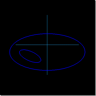
  • Create a full ellipse by select three points.
  • Create a full ellipse by picking the center point and radius point.

Key Points

  • Creates an ellipse by picking three points.
  • Creates an ellipse by picking the center point, the primary axis point, and the secondary axis point.
  • Play the video to see a demonstration of how to create two different types of ellipses. Do not adjust your volume; there is no sound associated with this video.

Prerequisites

  • Solid Edge must be in the Profile mode. Profile mode is automatically activated when creating a sketch feature or creating a profile for a feature.

Process: Creating an Ellipse By Three Points

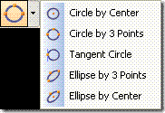
1. clip_image004[1] Click Ellipse by 3 Points from the Circle fly-out on the Draw toolbar. clip_image011
2. In the Graphics window, pick the first point of the ellipse. A dashed line displays connecting the point to the cursor.

3. Pick the second point, an ellipse displays between the two points.

4. Pick the third point to define the height and create the ellipse.

Process: Creating an Ellipse By Center and Endpoints

1. clip_image005[1] Click Ellipse by Center from the Circle fly-out on the Draw toolbar. clip_image011[1]

2. In the Graphics window, pick the first point of the ellipse. A dashed line displays connecting the point to the cursor.

3. Pick the second point, an ellipse displays between the two points.

4. Pick the third point to define the height and create the ellipse.

Tips

  • Ellipses are difficult to fully constrain. Use them only if necessary.