Overview:

A Revolved Protrusion is a feature that adds material to a solid. The profile that is created for a revolved protrusion is revolved about an axis. Let's review some of the options that are particular to a revolved protrusion.
 Axis of Revolution
When creating a profile for a revolved protrusion, you must identify one of the lines as the Axis of Revolution. The Axis of Revolution icon is located on the Features and Relationships toolbar. This option converts a line into an axis of revolution and changes the font to a centerline.

Extents.
When creating a revolved protrusion, there are two extent options available, 360 Degrees and Finite Extent. The 360 Degrees option creates a full revolution. If this option is selected, no other input is required. The default option is called Finite Extent. This option defines the protrusion with an angle value from the profile. To define the angle, you have three options.

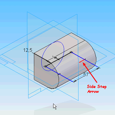
Option 1 is to drag the cursor to the approximate location and pick the location in the graphics window. The step distance can be changed to increase or decrease angle increment. It defaults to every 5 degrees.

Option 2 is to type in a value in the Angle text box and press ENTER on the keyboard. After the distance is entered, pick the location to determine the direction of the revolved protrusion.
Option 3 is to pick a keypoint. The keypoint option can be end point, mid point, arc center, or tangent point on the solid. The revolved protrusion is then linked to that keypoint and is modified when the keypoint moves.
Symmetrical/Non-Symmetrical.
With any revolved protrusion, you can use the Symmetrical or Non-Symmetrical Extent option for the Finite Extent. The Symmetrical Extent option would rotate the feature evenly on either side of the profile. The Non-Symmetrical Extent allows you to define the start and end angles relative to the profile.
Play the video for an overview of Revolved Protrusions. This file contains sound, so be sure to adjust your volume accordingly.